
Wanted to get this LC Technology WiFi Relay X4 with Nuvoton MS51FB9AE controller working with Tasmota. It took a bit of tinkering but with the following changes do have it running.
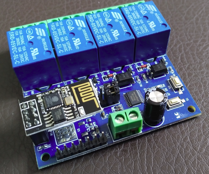
After flashing the ESP01 module supplied with the board with Tasmota the following configuration changes made the module working with the 4 onboard relays so they can be configured with your home automation controller.
Configuring the template:
Name
Based On
GPIO0, 2 , 4 and 5
GPIO1
GPIO3
GPIO9 and higher
LC-ESP01-4R-5V
4 Channel (13)
User
Serial Tx
Serial Rx
None
After configuring the above a rule needs to be added in the console, copy the below code and paste it within the console of Tasmota:
Rule1
on System#Boot do Backlog Baudrate 115200 endon
on SerialReceived#Data=41542B5253540D0A do SerialSend5 5749464920434f4e4e45435445440a5749464920474f542049500a41542b4349504d55583d310a41542b4349505345525645523d312c383038300a41542b43495053544f3d333630 endon
on Power1#State=1 do SerialSend5 A00101A2 endon
on Power1#State=0 do SerialSend5 A00100A1 endon
on Power2#State=1 do SerialSend5 A00201A3 endon
on Power2#State=0 do SerialSend5 A00200A2 endon
on Power3#State=1 do SerialSend5 A00301A4 endon
on Power3#State=0 do SerialSend5 A00300A3 endon
on Power4#State=1 do SerialSend5 A00401A5 endon
on Power4#State=0 do SerialSend5 A00400A4 endon
In order to turn on the rule enter ‘Rule1 1’ in the console and you should be good to go.
Getting this to work was partly based on the following page found on Tasmota’s Github pages: https://tasmota.github.io/docs/devices/LC-Technology-WiFi-Relay/
 I’ve had this receiver for quite a while now and it served me well but lately it started acting up where the center speaker and the subwoofer would start to drop out from time to time. The usual hit would bring it back and there was always a clicking sound when it happened. The clicking sound normally is related to electronic relays which are shown in the first picture (The blue ‘boxes’ are the relays in this case). A little bit of searching on the internet revealed that contact problems are a known problem with this receiver and resoldering the connection points of the relays fixes the problem.
 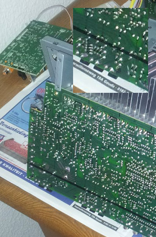 Once I opened up the receiver there are three relays which I suspect each controls two channels of the receiver being center and sub (and my problem area), front left and right and as last rear left and right. In order to fix the problem you will have to take the whole unit apart, if you aren’t sure you can piece it together use a digital camera or a smartphone to take some pictures before you start so you can see where all connections went. After you removed all the components and have the main PCB in front of you, you can look at the front side where the relays are and on the back which connections need your attention. Each relay has six connections and just heating them up should be enough. In my case I needed some additional tin for one of the connections, maybe this will be the case for you too. After finishing this you can assemble the unit and test the fruits of your labour. So far it is working out for my unit just fine.