Using an array rather than the incremental value that is now published on the mysensors.org website. This array method was used in the older version of the relay sketch before the upgrade to version 2.0. In order for upgrading from 1.5 to 2.0 for the relay boxes I’ve build it is far easier to stick to the the array method as most have an single relay board with eight relays on it which doesn’t fit in the current sketch any more.
/*
 * The MySensors Arduino library handles the wireless radio link and protocol
 * between your home built sensors/actuators and HA controller of choice.
 * The sensors forms a self healing radio network with optional repeaters. Each
 * repeater and gateway builds a routing tables in EEPROM which keeps track of the
 * network topology allowing messages to be routed to nodes.
 *
 * Created by Henrik Ekblad <henrik.ekblad@mysensors.org>
 * Copyright (C) 2013-2019 Sensnology AB
 * Full contributor list: https://github.com/mysensors/MySensors/graphs/contributors
 *
 * Documentation: http://www.mysensors.org
 * Support Forum: http://forum.mysensors.org
 *
 * This program is free software; you can redistribute it and/or
 * modify it under the terms of the GNU General Public License
 * version 2 as published by the Free Software Foundation.
 *
 *******************************
 *
 * REVISION HISTORY
 * Version 1.0 - Henrik Ekblad
 *
 * DESCRIPTION
 * Example sketch showing how to control physical relays.
 * This example will remember relay state after power failure.
 * http://www.mysensors.org/build/relay
 *
 *******************************
 *
 * UPDATES
 * Version 1.1 - Eugene Dullaard
 *
 * DESCRIPTION
 * This version uses an array of defined PINs like the v1 example
 * sketch did, instead of a startpin and counting from there.
 * The example is currently setup for Arduino Nano with 12 Relays
 * configured. Debugging and repeater is turned off.
 */

// Enable debug prints to serial monitor
//#define MY_DEBUG

// Enable and select radio type attached
#define MY_RADIO_RF24
//#define MY_RADIO_NRF5_ESB
//#define MY_RADIO_RFM69
//#define MY_RADIO_RFM95

// Enable repeater functionality for this node
//#define MY_REPEATER_FEATURE

#include <MySensors.h>;

/* Just adjust the number of relays to your need, the Maximum is twelve
 * There is no need to adjust the amount in the RELAY variable inless
 * you want to change the order in pins as used in your project.
 * As a reminder pins A6 and A7 are analog only and cannot be used.
 */

const int RELAY[] = {3, 4, 5, 6, 7, 8, A0, A1, A2, A3, A4, A5}; // I/O pins for the relays
#define NUMBER_OF_RELAYS 12 // Total number of attached relays
#define RELAY_ON 0  // GPIO value to write to turn on attached relay
#define RELAY_OFF 1 // GPIO value to write to turn off attached relay


void before()
{
    for (int sensor=1, pin=0; sensor<=NUMBER_OF_RELAYS; sensor++, pin++) {
        // Then set relay pins in output mode
        pinMode(RELAY[pin], OUTPUT);
        // Set relay to last known state (using eeprom storage)
        digitalWrite(RELAY[pin], loadState(sensor)?RELAY_ON:RELAY_OFF);
    }
}

void setup()
{

}

void presentation()
{
    // Send the sketch version information to the gateway and Controller
    sendSketchInfo("Relay", "1.1");

    for (int sensor=1; sensor<=NUMBER_OF_RELAYS; sensor++) {
        // Register all sensors to gw (they will be created as child devices)
        present(sensor, S_BINARY);
    }
}


void loop()
{

}

void receive(const MyMessage &message)
{
    // We only expect one type of message from controller. But we better check anyway.
    if (message.getType()==V_STATUS) {
        // Change relay state
        digitalWrite(RELAY[message.getSensor()-1], message.getBool()?RELAY_ON:RELAY_OFF);
        // Store state in eeprom
        saveState(message.getSensor(), message.getBool());
        // Write some debug info
        Serial.print("Incoming change for sensor:");
        Serial.print(message.getSensor());
        Serial.print(", New status: ");
        Serial.println(message.getBool());
    }
}
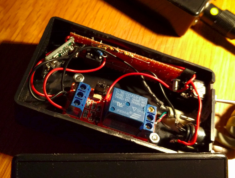
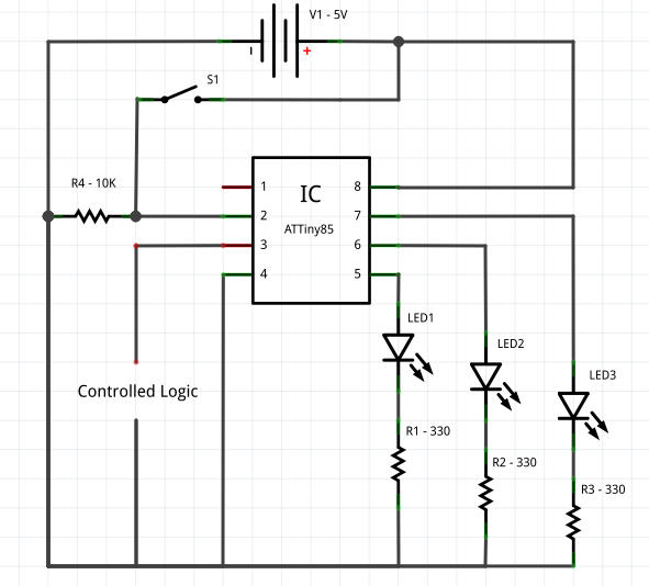 Total times works in the same way as binary, given the value in the code is 20, the first LED is 20, the second 40(2x) and the last 80(4x). Now by pressing the button you can choose between 20 to 140 minutes of delay before it switches off the timer. There is also a random time function which is activated when all LEDs are turned off, this will pick a random time between 40(2*) and 140(7*). As the amount of i/o is limited I’ve used an ATTiny85 rather than a complete Arduino, by modifying which pins it is using the code can be used on an Arduino as well.